WSW Technology Knowledge: Measuring Instrument for Pocket Hole Vertical Difference of Cylindrical Roller Bearing Cage
A self-developed instrument for measuring the pocket hole vertical difference of cylindrical roller bearing cage
Abstract: a self-developed instrument for measuring the pocket hole vertical difference of cylindrical roller bearing cage is introduced. The instrument structure, measurement method and principle are given. The application shows that the instrument has flexible adjustment, high measurement accuracy and meets the design requirements.
Key words: cylindrical roller bearing; Cage; Vertical difference of pocket; measure
As an important part of rolling bearing, cage has higher and higher precision requirements. However, the detection methods of cage are relatively backward, especially for the detection of the equal difference, vertical difference (or inclination), pocket position difference of cage pocket for high-precision and high-speed bearings. The vertical difference measurement of cylindrical roller bearing cage pocket is the same as that of other cylindrical rolling element cages. At present, there is no unified and standard instrument in the bearing industry, and all bearing manufacturers are exploring.

1 Current situation and problems
There is no reliable and effective method to measure the shape and position accuracy of the cage pocket of cylindrical roller bearing. For a long time, the machining accuracy of cylindrical roller bearing cage pocket basically depends on tooling positioning and broach or drill to ensure the dimensional and geometric tolerance, and the vertical difference of pocket is also basically controlled by the tool. In the process of machining, due to the influence of some factors such as uneven broach wear or low tooling positioning accuracy, the vertical difference of cage pocket is out of tolerance, which is difficult to ensure the stability of machining accuracy.
However, due to the limitations of the current measurement methods and instruments, such products cannot be accurately detected, resulting in the flow of unqualified products into the next process. During the use of the bearing, the rollers incline in the cage pocket, so that the plain lines of the rollers and the inner and outer raceways of the ferrule are no longer on the same section, affecting the rotation flexibility, assembly accuracy and service life of the bearing. Moreover, in the process of use, the high-speed rotating roller will move to the retaining edge due to the tangential force, the axial force of the roller will increase, the friction of the working part will increase, and the bearing temperature will rise in serious cases, even causing premature fatigue failure of the retaining edge, raceway and roller.
2 Structure of measuring instrument
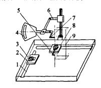
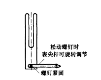
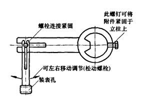
After analysis, experiment and research, the measuring instrument shown in Figure L is designed. First, process the stop L and stop 2, use the height instrument M716 as the base, and use T-shaped screws to fix two stops at the T-shaped groove of the instrument panel according to the needs of measuring positions of different types of cages. The relative positions of the two stops can be adjusted according to the T-shaped groove; On the top of the stop 2, screw a 90. The elbow fulcrum (Fig. 2) shall have a certain rigidity. In order to make the elbow fulcrum not easy to wear and prevent scratching the cage, a measuring meter tip shall be installed at the tip of the elbow fulcrum. During operation, use T-shaped bolts to press the elbow fulcrum on the stop 2 to maintain stability. According to the adjustment needs of the tested cage, the height between the elbow fulcrum and the instrument panel can be adjusted with gaskets. The length of the fulcrum extending out of the stop 2 and the left and right rotation can also be adjusted by loosening the T-shaped bolts; An instrument accessory (Figure 3) capable of installing a measuring meter is designed. The instrument accessory can slide up and down with the instrument column according to the measurement needs, so as to drive the instrument to slide up and down for measurement. When it is adjusted to a suitable position, the screw can be tightened to fix it on the column. A right angle meter tip is installed on the measuring meter to facilitate measurement and adjustment; Process and identify a height standard block, and use the height standard block as the measurement standard to ensure that the vertical difference of the height block meets the reference requirements required for measurement.

1. Altimeter platform; 2 one stop 1; 3 one compression screw; 4. Measurement table; 5 ~ elbow fulcrum; 6 - instrument accessories (sliding up and down); 7 a right angle tip; 8 one stop 2; 9 one standard block
Figure 1 Schematic diagram of measuring instrument

Figure 2 Schematic diagram of elbow fulcrum components

Fig. 3 Diagram of instrument accessories
3 Measurement method
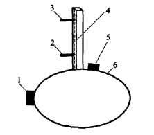
As shown in Figure 4, place the cage on the table so that the outer diameter of the bottom surface of the cage is close to the stop 1 and stop 2. Rotate the cage to the left so that the elbow fulcrum is against the lower end face of the pocket beam. At this time, the cage cannot continue to rotate to the left. Fix the elbow fulcrum at this position to achieve positioning. Then align the gauge with the standard height block, adjust the right angle gauge tip and the elbow fulcrum in a straight line, and measure the vertical difference of the cage pocket beam within the unit distance through the up and down sliding adjustment of the right angle gauge tip.

1 one stop L; 2 an elbow fulcrum; 3 a right angle tip; 4 - cage pocket beam (standard height block); 5 one stop 2; 6 outer diameter surface of cage bottom
Figure 4 Schematic diagram of measurement principle
4 Conclusion
The instrument has flexible adjustment and low cost, which improves the measurement efficiency and stability of the vertical difference of the cage pocket of cylindrical roller bearing, and can adjust the processing technology according to the measurement results to achieve the purpose of controlling the quality of cage products, so as to further improve the total body mass of bearing products.
More about WSW Cylindrical Roller Bearing:
The roller of cylindrical roller bearing is in line contact with the raceway and has large radial bearing capacity. It is suitable for bearing heavy load and impact load. Low friction coefficient, suitable for high speed, and the limit speed is close to the deep groove ball bearing. N-type and nu type can move axially, can adapt to the change of relative position between shaft and shell caused by thermal expansion or installation error, and can be used as free end support. The inner ring or outer ring can be separated for easy installation and disassembly. The processing requirements for the shaft and seat hole are high. After the bearing is installed, the relative deviation of the axis of the inner and outer rings shall be strictly controlled to avoid contact stress concentration. Double row cylindrical roller bearing with 1:12 taper in inner hole has adjustable radial clearance and high radial stiffness, which is suitable for machine tool spindle.

WBM are professional taper roller manufacturers and suppliers in China, with bulk high-quality products in stock. If you are going to buy a customized taper roller at a competitive price, welcome to get a quotation from the WBM factory. In line with the business philosophy of pursuing excellence, continuous improvement and common prosperity, the ball header, solid steel balls, roller header produced from WBM is absolutely high-quality and inexpensive.

