WSW Technology Knowledge: Research of Matching Installation Technology for Single Row Tapered Roller Bearings
The determination method of zero clearance of back-to-back paired single row tapered roller bearing, three measurement methods of inner spacer width under zero clearance are introduced and compared.

Abstract: The determination method is described for back to back matched single row tapered roller bearings with zero clearanc. The measurement method is introduced for width of inner ring spacer under three kinds of zero clearance, and the three measurement methods are compared. The results show that the third method is accurate and suitable, the measurement error is analyzed, and the corresponding solving measures are put forward to improve assembly quality.
Key words: tapered roller bearing; match; clearance; bearing assembly; inner ring spacer match grinding,wind power gear bearing, single row tapered roller bearing
1. Introduction
The back-to-back matching structure of single row tapered roller bearing not only has good rigidity, but also has good guiding accuracy, but also can bear overturning torque. Therefore, it has been more and more widely used in wind power gearbox. This bearing configuration mode is mainly applied to planetary gears, including traditional planetary gear structure and planetary gear structure using flexible pin technology. The planetary gear structure using flexible pin technology is shown in Figure 1.

Fig. 1 Technical bearing configuration of flexible pin shaft
After the matching of single row tapered roller bearings, the adjustment of axial clearance is completed by grinding the inner spacer. If the inner spacer is processed and adjusted by the bearing manufacturer, the cost is high and the installation clearance changes greatly. Therefore, the processing of the inner spacer and the adjustment of axial clearance are completed by the gearbox manufacturer. At present, the planetary gears of wind power gearbox configured with this bearing structure adopt negative clearance, and the axial clearance is generally - 0.1 ~ 0 mm. Although this bearing configuration has the characteristics of simple structure and flexible assembly, its installation process is complex, and the installation accuracy will affect the operating stiffness and service life of the bearing.
For batch production in the workshop, the adjustment of axial clearance is the key factor affecting production efficiency and product quality, and the adjustment of axial clearance is realized by grinding the inner spacer. Therefore, it is necessary to find a convenient and fast measurement method to determine the width of the inner spacer. At present, various wind power gearbox manufacturers have different measurement and installation methods for the bearing structure configuration. Here, several measurement methods of inner spacer width will be compared and analyzed to determine an accurate and fast measurement and installation method, and give suggestions on the optimization of travel star wheel structure.
2. Determination of Zero Clearance
When adjusting the installation of a pair of back-to-back tapered roller bearings, the bearing must be rotated to make the roller in the correct position, that is, the large end face of the inner assembly roller is tightly pressed against the large retaining edge of the inner ring, and the outer ring raceway is tightly pressed against the roller cone. At this time, it is the zero clearance state of the tapered roller bearing.
As shown in Figure 2, install bearings a and B in place, put the whole planetary gear part on the platform, and rotate the planetary gear until it runs smoothly. At this time, the large end face of bearing B roller is tightly pressed against the large retaining edge of the inner ring, and there is a gap between the large end face of bearing a roller and the large retaining edge of the inner ring. It can be easily inserted with a feeler gauge of 0.1 ~ 0.15 mm. Therefore, it can be determined that bearing B is in the state of zero clearance and bearing a is in the state of non-zero clearance.
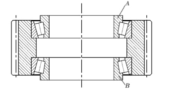
Fig. 2 zero clearance state
3. Determination of Inner Spacer Width
The key to adjusting the axial clearance is to determine the width of the inner spacer under the condition of zero clearance. Set the width of the inner spacer under the condition of zero clearance as L0 and the required clearance as δ 0, then the width l of the inner spacer after installation is
L = L0+ δ 0
If the width of the inner spacer in the initial state is L1, the grinding amount of the inner spacer Δ L is
Δ L = L1 - L
For the measurement of the width L0 of the inner spacer under the condition of zero clearance, each gearbox manufacturer adopts three different measurement methods.
3.1 Method 1
The measurement principle is shown in Figure 3. Put the planetary gear part on the platform, remove the inner spacer, add a load block on bearing A (the mass and structural design of the load block are not introduced here), rotate the planetary gear to a stable state, and directly measure the height H between the upper and lower bearings. H is the width L0 of the inner spacer in the state of zero clearance.
Bearing B is in the state of zero clearance under the action of planetary gear, load block and bearing gravity, but bearing A is in the state of non-zero clearance due to the self-locking effect of the cone of the inner assembly. There is a certain clearance between the roller ball base surface and the retaining edge of the inner ring. At this time, if the height H is taken as the width L0 of the inner spacer under the state of zero clearance, there will be a large error in the measurement result.
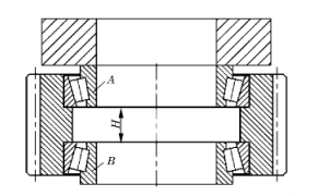
Fig. 3 Schematic diagram of method 1 Measurement
3.2 Method 2
The measurement principle is shown in Figure 4. First, take any one of the two paired sets of bearings and mark it. Measure the assembly widths T1 and T2 of the bearings in the positive and negative states, and calculate the difference between them δ 1, i.e δ 1 = T1 - T2, δ 1 is the error value of bearing a in Fig. 4b when measuring the axial clearance of paired bearing under the condition of non-zero clearance (load block shall be added when measuring T1 and T2)
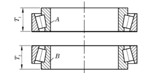
(a) Bearing assembly width measurement
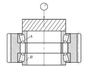
(b) measuring principle
Take out the inner spacer, add a load block on bearing A, make the probe hit the center of the load block, rotate the planetary gear to a stable state, and bearing B is in the state of zero clearance. At this time, set the measuring instrument to zero and move the planetary gear sleeve out of the measuring area. Then install the inner spacer without grinding, add the load block again, put the probe of the measuring instrument in the center of the load block, rotate the planetary gear to a stable state, and record the reading of the measuring instrument δ 2. At this time, the axial clearance of the paired tapered roller bearing can be calculated Δδ, Namely Δδ = δ 1 + δ 2, then the width of the inner spacer in the state of zero clearance L0 = L1+ Δδ.
3.3 Method 3
The measurement principle is shown in Figure 5. Put the planetary gear part on the platform, remove the inner spacer, put the bearing A on the upper part, rotate the planetary gear to a stable state, and measure the height H1 from the upper end face of the planetary gear to the end face of the inner ring of bearing B; Then turn over the planetary gear so that bearing B is located at the upper part, rotate the planetary gear to a stable state, and measure the height H2 from the end face of the planetary gear to the end face of the inner ring of bearing A. Assuming that the width of the planetary gear is K, the width L0 of the inner spacer in the state of zero clearance is
L0 = H1 + H2 - K
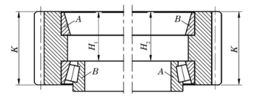
Fig. 5 Schematic diagram of method 3 measurement
Comparing the above three measurement methods, it is found that although the measurement process of method 1 is simple, there is a large measurement error, and the different mass of the load block has a great impact on the measurement results. Method 2 eliminates the error of axial clearance when measuring the upper bearing in non-zero clearance state, but it needs to be measured δ 1. The whole measurement process is long, and the error generated by the instrument during the first and second measurements cannot be ignored. Compared with the first two methods, measurement method 3 has less measurement data and less error in the whole measurement process, which is more suitable for batch production in the workshop.
4. Error Analysis and Countermeasures
Compared with the above measurement methods and combined with the installation process of planetary gear components, the error in the measurement process of method 3 is analyzed and the countermeasures are given.
Method 3 in the measurement process, when measuring data K, H1 and H2, due to the end face runout and parallelism tolerance of the two end faces of the planetary gear and the end face of the inner ring of the bearing, there will be certain errors in the measurement process. Generally, the end face runout of the planetary gear is less than 0.03 mm, and the perpendicularity of the bearing end face relative to the inner hole is smaller. Therefore, the method of taking the average value of multi-point measurement can be used in the measurement. During installation, in order to improve production efficiency and ensure the accuracy of measurement, 4 ~ 6 points can be taken for measurement, and the average value can be taken as the final measurement value of K, H1 and H2.
In addition, in order to facilitate the measurement of H1 and H2, when designing the planetary gear, ensure that the end face of the bearing inner ring is lower than the end face of the planetary gear, that is, there is a certain height difference between the bearing end face and the end face of the planetary gear γ, As shown in Figure 6.
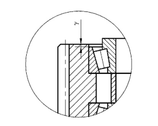
Fig. 6 planetary gear structure optimization
Due to the interference fit between the outer ring of the bearing and the inner hole of the planetary gear, the planetary gear is heated for hot assembly during installation. During the cooling process of the planetary gear, there will be a certain gap between the end face of the outer ring of the bearing and the retaining edge of the inner hole of the planetary gear. The measured gap value during field installation is about 0.02 ~ 0.05 mm. The existence of this gap will affect the axial clearance value of the paired bearing. When the bearing outer ring is installed in place and cooled slowly, the end face of the bearing outer ring can be in close contact with the retaining end face of the inner hole of the planetary gear by applying pressure, as shown in Figure 7. The application of heavy objects on a single planetary gear or the superposition of two or more planetary gears can ensure that the end face of the bearing outer ring is in close contact with the retaining edge of the inner hole of the planetary gear during the cooling process of the planetary gear and improve the installation quality.

Fig. 7 improvement of installation process of planetary gear sleeve
5. Calculation Example
Taking the back-to-back paired installation bearing composed of two sets of 32040 tapered roller bearings as an example, the installation process of the bearing and the determination process of the width of the inner spacer are explained.
32040 bearing width T = 70 mm, planetary gear width K = 170 mm, inner hole retaining edge width K1 = 60 mm. The axial clearance required for back-to-back installation is - 0.1 ~ 0 mm.

Match the bearing inner and outer rings, heat the planetary gear to a certain temperature, install the two bearing outer rings into the planetary gear inner hole, ensure that the end face of the bearing outer ring is close to the edge of the planetary gear inner hole, and place the planetary gear part sleeve according to the requirements of Figure 7 until the planetary gear cools down. Use a feeler gauge to check whether there is a gap between the end face of the outer ring of the bearing and the retaining edge of the inner hole of the planetary gear. If the gap is too large, reinstall it.
Place the planetary gear part sleeve on the measuring platform and measure according to the requirements of method 3. When measuring K, H1 and H2, take the average value of 6 measuring points evenly distributed on the circumference, and the measured results are 170.12, 115.05 and 115.02 mm respectively. Then, under the condition of zero clearance, the width of the inner spacer L0 = H1 + H2-K = 59.95 mm, and the axial clearance is required to be - 0.1 ~ 0 mm, then the width of the final installed inner spacer L = L0 + δ 0 = 59.85 ~ 59.95 mm, that is, the width of the installed inner spacer is within 59.85 ~ 59.95 mm, which can meet the requirements of the axial clearance of the paired bearing. If the initial width of the inner spacer L1 = 61 mm, the inner spacer needs to be ground off Δ L = L1 - L = 1.05 ~ 1.15 mm.
6. Conclusion
Through the analysis of the planetary gear installation process and measurement process, it can be found that method 3 is accurate and fast, which is of great significance in improving product production efficiency and product quality. In addition, in the design of planetary gear parts, the convenience of installation and measurement of subsequent products must be considered, and corresponding optimization measures shall be taken.
More about WSW Tapered Roller Bearings:
WSW tapered roller bearing belongs to separate bearing, and the inner and outer rings of the bearing have tapered raceways. This type of bearing is divided into single row, double row and four row tapered roller bearings according to the number of rows of rollers installed. Single row tapered roller bearings can withstand radial load and axial load in a single direction. When the bearing bears radial load, an axial component will be generated, so another bearing that can bear the axial force in the opposite direction is needed to balance.
Features and benefits of WSW tapered rollers:
1) Low friction, noise, and vibration
2) Long service life
3) Enhanced operational reliability even under difficult conditions
4) Running-in period with reduced temperature peaks
5)Separable and interchangeable components help to facilitate mounting, dismounting and maintenance

Wafangdian Guangda Bearing Company is a comprehensive enterprise, which is a collection of bearing D&R, production and selling, and has passed ISO9001-2000 quality management system certification. Now it can produce various types of bearings, over 200 series and 5,000 designations or so. For example, deep groove ball bearings, spherical ball bearings, cylindrical roller bearings, self alining roller bearings, angular contact ball bearings, tapered roller bearings, thrust ball bearings, thrust roller bearings, spherical plain bearings, car hub bearings, slewing bearings and British series bearings and so on. It can also design and produce various types of non-standard bearings according to customers’ different requirement. Products are widely used in metallurgy, mining, petroleum, chemical industry, machinery, vehicles, papermaking, cement industries etc, and exported to Europ, USA and South Asia market and gained cuctomers’ recognition at home and abroad.

